Ordering of cuts in 2D Gmsh-GetDP (homology-cohomology)
Dear all,
This is not per se an issue but an inconveniency in some cases. I am running a case study 1n 2D having different conductors in series.
For each conductor, I assign a cut to impress the transport current. As all the conductors are in series, they have the same current. However, building the cuts and assigning the current result in random orientation of the latter. It seems that the edges of the mesh making the cuts are not necessary in the same "direction" for all overlapping cuts.
A colleague of mine as a manual fixed reordering the direction of the edges, however, I think tat it would be more appropriate to have it already arranged directly in the code. The idea would be that the direction of the cuts are all the same for all the conductors and only the sign of the impressed current should be defined.
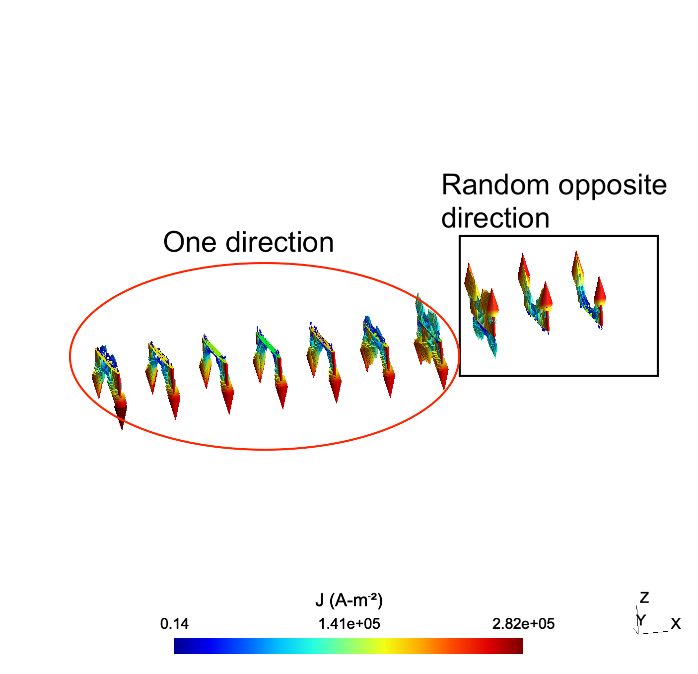
I am attaching a figure showing the current density resulting of impressing the current through the cuts with the basic ordering of Gmsh.
The cuts are associated with branches in an electrical circuit each branch is a conductor form node 2 to 11:
{ Region cut_0; Branch{2, 3}; } { Region cut_1; Branch{3, 4}; } { Region cut_2; Branch{4, 5}; } { Region cut_3; Branch{5, 6}; } { Region cut_4; Branch{6, 7}; } { Region cut_5; Branch{7, 8}; } { Region cut_6; Branch{8, 9}; } { Region cut_7; Branch{9, 10}; } { Region cut_8; Branch{10, 11}; } { Region cut_9; Branch{11, 0}; }
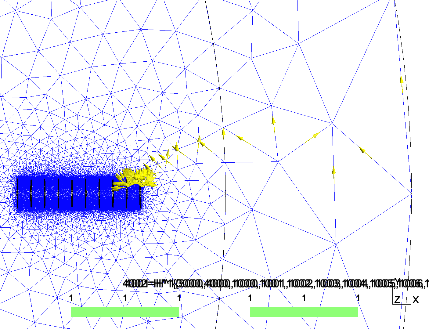
Some of the cuts:
Current density:
Best,
Frederic